- 您现在的位置:买卖IC网 > Sheet目录319 > CS4161YN8 (ON Semiconductor)IC DRIVER H-BRDG DUAL 85MA 8DIP
�� �
�
�CS4161�
�CIRCUIT� OPERATION�
�SPEED� SENSOR� INPUT�
�SENSOR� is� a� PNP� comparator� input� which� accepts� either�
�The� polarity� definition� for� the� coil� driver� outputs� is� as�
�follows:�
�a� sine� wave� or� a� square� wave� input.� This� input� is� protected�
�from� excursions� above� V� CC� as� well� as� any� below� ground� as�
�long� as� the� current� is� limited� to� 1.5� mA.� It� has� an� active�
�clamp� set� to� zero� volts� to� prevent� negative� input� voltages�
�Polarity�
�Positive� (+)�
�Negative� (–)�
�Connect� Coil� +�
�V� CC�
�GND�
�Connect� Coil� –�
�GND�
�V� CC�
�from� disrupting� normal� operation.� The� sensor� input� can�
�withstand� 150� V� DC� as� long� as� the� input� current� is� limited� to�
�1.5� mA� max.� using� a� series� resistor� of� 100� k� ?� .�
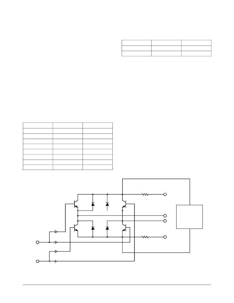
�COIL� DRIVER� OUTPUTS�
�DIVIDER� SELECT� INPUT�
�The� speed� sensor� input� frequency� is� either� divided� by� one�
�or� divided� by� two� depending� on� the� state� of� the� SELECT�
�Simultaneously� energizing� the� source� and� sink� on� either�
�leg� is� not� permitted,� i.e.� Q1� &� Q2� or� Q3� &� Q4� cannot� be�
�energized� simultaneously.�
�Circuit� function� is� not� affected� by� inductive� transients� due�
�to� coil� loads� as� specified� in� the� Transition� States� section.�
�The� transition� states� occur� as� indicated� in� Table� 1� without�
�any� intermediate� states� permitted.�
�Table� 1.� Transition� States�
�input� as� follows:�
�Logic� 0� =� divide� by� 2.�
�Logic� 1� =� divide� by� 1.�
�State�
�0�
�1�
�2�
�3�
�4�
�5�
�6�
�7�
�Coil� A�
�+�
�OFF�
�–�
�–�
�–�
�OFF�
�+�
�+�
�Coil� B�
�+�
�+�
�+�
�OFF�
�–�
�–�
�–�
�OFF�
�Short�
�Circuit�
�Sense�
�V� CC�
�Q1�
�Q2�
�Q3�
�Q4�
�Resistor�
�Short�
�Coil�
�Overvoltage�
�and�
�Short� Circuit�
�Protection�
�Circuit�
�GND�
�Sense�
�Resistor�
�Figure� 2.� Coil� Driver� Output�
�http://onsemi.com�
�4�
�发布紧急采购,3分钟左右您将得到回复。
相关PDF资料
CS5461A-ISZ
IC ENERGY METERING 1PHASE 24SSOP
CS5462-ISZ
IC ENERGY METERING 1PHASE 24SSOP
CS5463-IS
IC PWR/ENERGY METER 2CH 24-SSOP
CS5464-IS
IC PWR/ENERGY METER 3CH 28-SSOP
CS5466-ISZR
IC ENERGY METERING 1PHASE 24SSOP
CS5466-IS
IC ENERGY METERING 1PHASE 24SSOP
CS8312YN8
IC PREDRIVER IGBT IGNITION 8DIP
CX1006
SOCKET ADAPTER 40TSOP SUPERPRO5K
相关代理商/技术参数
CS4172
制造商:CHERRY 制造商全称:CHERRY 功能描述:Single Air-Core Gauge Driver
CS4172/D
制造商:未知厂家 制造商全称:未知厂家 功能描述:Single Air-Core Gauge Driver
CS4172DW16
制造商:未知厂家 制造商全称:未知厂家 功能描述:Meter Driver
CS4172DWR16
制造商:未知厂家 制造商全称:未知厂家 功能描述:Meter Driver
CS4172N16
制造商:未知厂家 制造商全称:未知厂家 功能描述:Meter Driver
CS4172XDWF16
制造商:CHERRY 制造商全称:CHERRY 功能描述:Single Air-Core Gauge Driver
CS4172XDWFR16
制造商:ON Semiconductor 功能描述:
CS4172XN16
制造商:ON Semiconductor 功能描述: